Introduction
In this part we introduce the terms voltage, current, resistance, capacitance and inductance and explain how devices can be constructed to exhibit each of these properties. We also explore the relationships between current, voltage and resistance and define the direction of current flow within an electrical circuit.
The Voltage
The voltage, V, is the driving force in an electrical circuit. It acts on the free electrons contained within metallic wires and forces these charges to move around the circuit. Mathematically it is calculated using
| V = W/q |
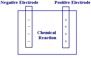
where W is the work done in moving the charge q. Its meaning can be understood by way of an analogy. When water is pumped from a reservoir to some holding tank above, work is done to fill the vessel and the water stores the work done as potential energy. The change in the potential energy (or potential difference) in taking the water from the receiver to the tank is analogous to the voltage in the electrical circuit and can be considered as the driving force to move the charge. One of the most common sources of voltage comes from a battery, which is typically composed of two electrodes separated by a chemical medium.

If designed appropriately the chemical medium can undergo reaction to establish a positive and negative charge on the electrodes. This separation of charge creates a potential difference which can be harnessed by connecting the two electrodes to an electrical circuit.
The Current
The current (i) is related to the movement of electrons through a circuit, typically induced by an applied voltage. The current is reported in units of amperes (amps) and is the rate of flow of charge:
| i = q/t |
The direction of electron flow in a circuit will be towards the positive terminal of the voltage source since this will be the attractive pole for the negatively charged electrons.
The Resistor
The resistance of a wire arises from the collisions of the moving electrons with atoms within the material. These collisions result in the loss of some of the energy of the electrons and is dissipated as heat in the wire. The resistance for a wire or other material of length l, area A and resistivity p can be calculated using the following expression
| R = pl/A |
The unit of resistance is the Ohm and is related to the current and voltage by Ohm's law:
| V = iR |
The Capacitor
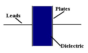
In its simplest form the capacitor is a device composed of two parallel plates separated by an insulating material - termed a dielectric. This device is unlike the resistor above as it is capable of storing charge. In its neutral form both plates contain the same number of free electrons

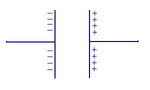
however when the capacitor is connected to a voltage source via an electrical circuit it is possible to move the free electrons from one plate to another. The net result is that one plate becomes positively charged and the other negatively charged.

The amount of charge that may be stored by the capacitor per unit of voltage is the capacitance C. The unit of capacitance is the farad (F) and is related to the charge and voltage in the following way
| C = q/V |
The Inductor
The inductor is another device which is capable of storing charge and in its simplest form is a coil of wire
![]()
When a current is passed through the wire the flow of charge around the loops creates a strong electromagentic field. The magnitude of this field is related to the total current flowing, an increase in the current increases the magnitude of the field, correspondingly a decrease in the current decreases the field. When an oscillating current is passed through the inductor this creates a changing electromagnetic field and this inturn creates an induced voltage. This can be represented mathematically as
| Vinduced = L(di/dt) |
where (L) is the inductance and takes the units of henry's (H). In the following sections we see how to construct and analyse electrical circuits composed of the above components.

