Introduction
In this final section we examine the frequency response of circuits containing resistors and capacitors in parallel combinations. As with the previous section we can use the DC analysis of resistor parallel circuits as a starting point and then account for the phase relationship between the current flowing through the resistor and capacitor components.
Analysing RC Parallel Circuits
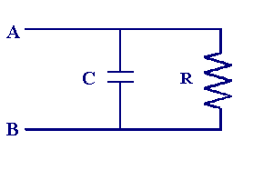
As we have seen previously in a parallel circuit the current has a number of alternative pathways to follow and the route taken depends upon the relative 'resistance' of each branch. The figure below shows a parallel combination of a single resistor and capacitor between the points A and B.

To calculate the total impedance (resistance) of this circuit we again use the capacitative reactance Xc as the equivalent resistance of the capacitor. Then we use the same rules introduced for summing resistors in series remembering that now we are dealing with phasor quantities. You will recall that the rule for summing resistors in parallel is given by
| 1/RT = 1/R1 + 1/R2 |
treating R2 above as the capacitative reactance and a little bit of complex number algebra we can show that the impedance magnitude and phase angle is given by the following


Now we will examine the response of a circuit as above with a capacitative reactance of 50 Ω and a resistance of 100 Ω
| Z = 100 x 50/(100 2 + 50 2)½ = 44.7° |
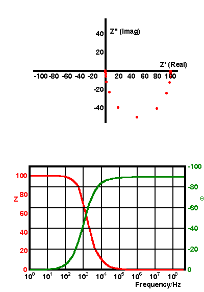
and the angle is -63.4°. The frequency response of this type of circuit is shown below in phasor and bode forms.

The phase angle is seen to change from 0° at low frequencies where the current flows almost completely through the resistor arm to -90° at high frequencies where the current flow is through the branch containing the capacitor.

