Introduction
In this section we examine the response of resistors, capacitors and inductors to an applied sinusoidal voltage. In each case we will consider the effect of the sinusoidal signal:
![]()
Resistor Circuits
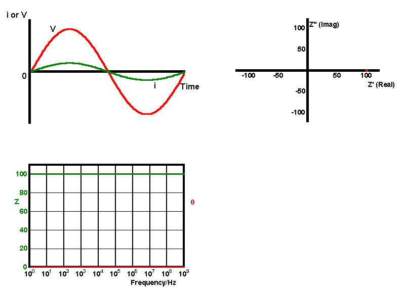
We begin our discussion with the simplest of the three components - the resistor. A sinusoidal voltage is applied across a circuit containing a single 100 Ω capacitor. The impedance response of the circuit is presented in the animation below using, time, phasor and bode plots.
| Circuit Component | Frequency Response |
| |
 |
The observed behaviour can be explained since the current at any point on the voltage curve is predicted by Ohms law, so the current is always proportional to the magnitude of the voltage
![]()
consequently there is no phase shift or frequency dependence for the resistor circuit. In Phasor representation this result gives a single point on the real axis corresponding to the resistance R at any frequency. The Bode plot shows the same information with the phase angle equal to zero and the magnitude of the impedance equal to R for the whole frequency range.
Capacitor Circuits
Next let us consider a single capacitor of capacitance C, here the relationship between the current flow and applied voltage is given by

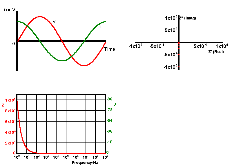
unlike the resistor, the current flow is proportional to the voltage gradient (with respect to time) and consequently this introduces a phase shift between the two. The impedance response for a circuit containing a single capacitor is shown in time, phasor and bode notations below.
| Circuit Component | Frequency Response |
| |
 |
clearly the current is 90° out of phase with the voltage, the Bode plot shows that this relationship holds for all frequencies although the magnitude of the signal drops as the frequency increases. To explain this behaviour we need to understand how the capacitor resists the passage of current. A measure of this resistance to current flow is given by the capacitative reactance Xc which has units of Ohms. This quantity Xc has both magnitude and phase and calculated using

it may be predicted by invoking Ohms law which tells us that the circuit resistance (in this Xc) is equal to
This shows us that the quantity ‹Xc always has a -90° angle attached to its magnitude and it's usually written as above or in the complex form -j Xc.
Inductor Circuits
Finally we consider the response of an inductor with an inductance (L). Here the relationship between the current flow and applied voltage is given by

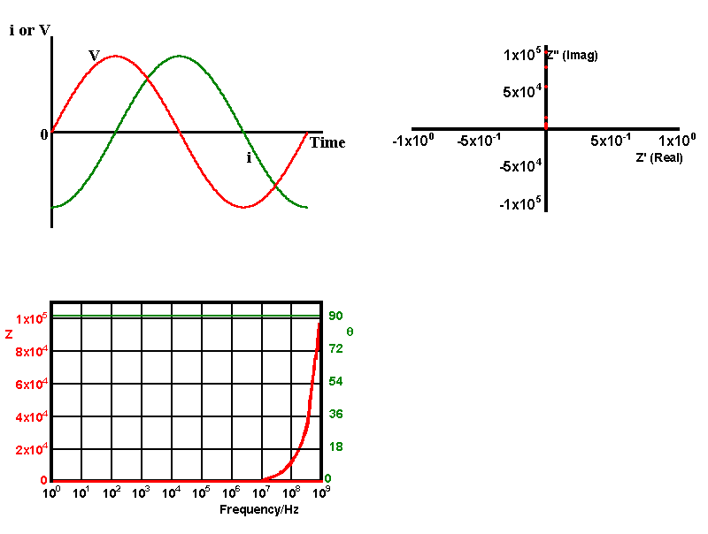
like the capacitor, the current can be seen to be out of phase with the voltage. The impedance response of a circuit containing a single inductor is shown below in time phasor and bode forms.
| Circuit Component | Frequency Response |
| |
 |
In an analogous manner to the capacitor the 'resistance' to current flow is given by the inductive reactance Xl which has both a magnitude and phase:
![]()
it may be predicted by using Ohms law which tells us that the circuit resistance (in this case Xl) is equal to

This shows us that the inductive reactance always has a 90° angle attached to its magnitude and is usually written in complex form as jXl or in polar form
![]()
We now have the basic information required to analyse circuits containing combinations of the above components in series or parallel. As the majority of circuits of interest in electrochemical analysis are combinations of resistors and capacitors we will only consider these in the later sections, although the extension to examine inductive circuits requires no further developments.

